This site documents my activities in the hobby of Amateur Radio. It is intended for a wide audience, not only for hams, but also, for those that might want get into the hobby.
Tuesday, March 29, 2016
My New Toy - ICOM 7300
Pulled the trigger on this on March 26, 2016 from Ham Radio Outlet. I have not been this excited in years!
REFERENCES:
Thursday, March 24, 2016
Antenna Analyzers
This post relates to antenna analyzers useful to amateur radio operators. I will list my experiences with these in this article.
Array Solutions AIM 4170
I don't recall what I paid for my AIM 4170. It is an older version and has been replaced with the AIM 4300 ($519). The AIM 4170 exceeded my expectations. It is well worth the price if you are doing any kind of antenna work or network characterization.
The software runs under Windows 7 and works very well. I have not tried to port it to Ubuntu.
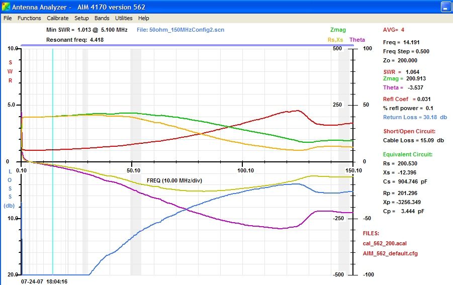
This plot is from an antenna feed balun I built. Here is a photo:
Labels:
AIM 4170,
antenna analyzer,
antennas,
array solutions,
balun,
rf
Driving a Balanced Antenna with an Unbalanced Coax - Why A Balun Is A Good Idea
In a recent conversation about the need for a balun on a dipole fed with coax, the comment was made that no balun is needed because the dipole radiates in a balanced manner.
Well, maybe...
If a dipole is positioned above uniform ground and there are no trees, hills, fences, buildings, or powerline poles, then the statement above might be.
However, the real world has trees, has hills, fences, wet and uneven ground, and powerline poles. It would be rare to have one side of a dipole driving the same free-space radiation impedance as the other side. If there is an unbalance, then the outer shield of the coax will radiate RF to make up the difference. An easy way to think of it is to imagine that one side of the dipole radiates 10 amps of RF and the other side radiates 9 amps due to the imbalance. The difference of 1 amp has to get made up. It gets radiated from the outside of the shield of the coax. Stated differently, the coax center conductor carries 10 amps. The inner shield carries 9 amps and the outer shield carries 1 amp.
An extreme case of this condition would be the feeding of an off-center fed dipole. Clearly, such a design is very much out of balance. A good example of this antenna as well as the method of feeding it is found at [7]. I have used this type of antenna many times in the field at campgrounds. The advantage is that the "long end" can be shot up over a tall pine tree and the short end tied off near the ground. The feed point is, then, relatively close to the operating position.
RF on the outside of the coax will radiate and may radiate RF inside the shack.
My favored method for driving a dipole is to feed it with coax and have a balun at the antenna feed point.[1][2]
Properly constructed, the balun will force all of the current coming out of the center conductor to equal the current returning on the inside of the shield. Common mode current is reduced to nearly zero.
This post prompts an idea for a project - a longitudinal RF ammeter. Feedline imbalance can be detected by measuring the current in both legs of the feedline. If there is a balance, the currents will be equal. An easier way is to construct an RF ammeter to directly measure the imbalanced current. Such a device is depicted in [7, 8].
REFERENCES:
- "Baluns: What They Do and How They Do It,", Roy W Lewallen, W7EL, http://www.eznec.com/Amateur/Articles/Baluns.pdf
- "Feeding a dipole using a balun", https://en.wikipedia.org/wiki/Dipole_antenna#Feeding_a_dipole_using_a_balun
- "A Cost Effective Current-mode 1:1 Balun", http://www.arising.com.au/people/Holland/Ralph/CMBalun.htm
- RF Current Meter http://vk6ysf.com/RF_Current_Meter.htm
- "A Transmission Line Balance Test Meter, "Lloyd Butler VK5BR", http://users.tpg.com.au/users/ldbutler/Line_Bal_Test_Meter.htm
- "Measurement of relativity between the Longitudinal and the Differential currents in the Transmission Line", Lloyd Butler VK5BR, http://users.tpg.com.au/users/ldbutler/Line_Diff_Long_Meter.htm
- "Array Solutions OCF Dipoles", "", https://www.arraysolutions.com/Products/ocf_dipole.htm
- "Study of the Off Centre Fed Dipole Antenna", "G8ODE", https://rsars.files.wordpress.com/2013/01/study-of-the-ocf-dipole-antenna-g8ode-iss-1-31.pdf
Tuesday, March 22, 2016
SDRPlay Radio Installation Notes
Overview
These notes pertain to the installation and implementation of an SDR (Software-Defined Radio) on Linux and Windows-based machines.
I was able to get the SDRPlay device installed for Windows and for Linux.
Windows Installation
Early on, my attempts to install SDR software on a Linux Ubuntu 14.04 machine failed due to, apparently, missing modules on the workstation.So, I decided that, if I could get it to run under Windows, it would prove that the device worked and would give me confidence that it could be installed under Linux.
The Windows 7 Pro installation went well and I was able to get an SDR running in that OS.
Linux Ubuntu 14.04 Installation
Linux was tricky.
The following links were useful to get this running:
- http://cubicsdr.com/
- http://sdrplay.com/linux.html
- https://github.com/cjcliffe/CubicSDR/wiki/Build-Linux
- http://www.sdrplay.com/linux.html
The order of the steps was not correct in the Build-Linux document. In short, the support modules, listed at the end of the document, must be compiled first before the other items. This is not, for a new user, an obvious requirement.
GNURadio Installation
These notes pertain to installing the GNURadio software.In short, I have no clue as to how this GNU Radio is useful. Today...
More later...
REFERENCES:
Wednesday, March 16, 2016
Friday, March 4, 2016
Operating Remote Receiver and Local Transmitter with Digital Modes
Over the past few years, many SDR receivers have been put online and can be accessed over the Internet. This allows one to monitor the bands from receive locations far from the operator's local area. This is very useful to determine if your signal is getting into an area. I have used it to monitor the Wyoming Cowboy Net from an SDR receiver in Sedona, AZ (http://w7rna.dyndns-remote.com:18901/).
It occurred to me that one could use a remote SDR receiver to counter problems with local noise. In order to test this concept, I've installed two programs on my Ubuntu 14.04 Linux box, as follows:
FLDIGI(1) - a powerful digital mode encoder/decoder program
PULSE AUDIO VOLUME CONTROL(2) - a software package that allows one to direct audio from various sources to various outputs.
Once these are installed, the web-based SDR receiver can be chosen from the site: websdr.org
The audio produced by the web page is routed, using the Pulse Audio application, to the FLDIGI software.
For my experiment, I connected to http://radman.no-ip.ca:8903/ (New Brunswick, Canada) and set the receive frequency to 14.070 MHz. There were many signals on the band and I was able to decode many, including SP6QKS (Poland), OK2MI (Czech Republic), F5POJ (France), and IU8ALH (Italy).
While I have a West Mountain Radio Rig Blaster Pro, I do not have it interfaced to my rig and have no plans to do so.
One other aspect of this method is the question of authenticity. When one operates an SDR receiver located in a remote area but transmits from a local area, does that bring into question the validity of the QSO? That is a question for another article.
REFERENCES:
ADDENDUM
- Working "split remote" will not work in contesting due to the delay. Much like Echolink in that sense. If you hear a station issue QRZ, your response will be too late.
- As is often the case, messing with sound cards with multiple inputs and outputs, it is easy to mess things up. In my case, on Ubuntu 14.04, the sound system selected "Dummy Output" for an output. Thus, no audio from the speakers. Google to the rescue, offering this sequence of commands that fixed it:
pulseaudio --kill
sudo alsa force-reload
pulseaudio --start
Sunday, February 28, 2016
Ham Radio and the Raspberry Pi
This post is an effort to collect resource links for the use of the Raspberry Pi with Amateur Radio.
This post will be updated with new links as time permits.
REFERENCES:
This post will be updated with new links as time permits.
REFERENCES:
Saturday, February 27, 2016
Directional Discontinuity Ring Radiator and Other Magnetic Loops (Part One)
I have been thinking for some time that I would like to operate on the 160 meter band. I have a loop antenna of, about 268 feet perimeter. It resonates between the 80M and 40M bands. As such, it is hard to tune in the 160M band and most of the power is used to warm up the tuner.
Recently, a friend of mine, Larry Anderton, WA7YLI, remembered an odd antenna called a Directional Discontinuity Ring Radiator. Never having heard of the antenna by that name, I researched the topic and found some useful references (see below).
Another friend, Jeff, McGrath, KG7HSN, has been searching for alternatives to large, highly visible, antennas in his yard. This antenna might be a solution.
A few days ago, I had a QSO with Rich, K8NDS, of Prescott, AZ on 40M. He was running about 500 watts into a magnetic loop antenna. He was S9+10dB here in Salt Lake City. His QRZ page shows aerial drone photos of his antenna farm. He has had incredible results with this kind of antenna and has written a paper on it. He has a Yahoo Group on this topic.
Both the DDRR antenna and the Helically Loaded Fractional Wave Antenna have been proven effective in various tests. While one could charge off and build either one, I am wondering if, somehow, the two designs could be combined? What would be the benefits? What would be lost in the mixing?
These are questions that I will explore in this and subsequent posts.
Stay tuned...
REFERENCES:
- "Circular Antennas," Popular Science, December 1962
- "Stealth Antennas for the Radio Amateur," Richard Fusinski, K8NDS
- KV4PN Magnetic Loops
- Yahoo Group - Helically Loaded Fractional Wave Antenna
- N5DUX PDF Files
- The_DDRR-Directional_Discontinuity_Ring_Radiator (pdf)
- Classic Rain Gutter Loop Antenna
- Horizontal Loop Antenna for Shortwave Listening and Amateur Radio Use (pdf)
- Copper Loops For 222 and 440 Mhz
- DDRR Antenna For The Car
- DDRR (Direct driven ring radiator) Modeling
- 2M DDRR Mobile Antenna
- Try Copper for 2 Meters - The Cu Loop (pdf)
- The Loop Skywire
PATENTS:
- Low profile antenna having horizontal tunable top loading member US 3427624 A
- Low profile antenna US 3247515 A
- Open ring antenna US 3151328 A
PHOTOS
Tuesday, January 26, 2016
Packet Radio on Raspberry PI
This post is a placeholder awaiting more detail.
I intend to setup a Raspberry PI, a Baofeng radio, and a Kamtronics KAM modem to handle NTS digital traffic.
More later...
I intend to setup a Raspberry PI, a Baofeng radio, and a Kamtronics KAM modem to handle NTS digital traffic.
More later...
Subscribe to:
Posts (Atom)